Table of Contents
Introduction
Within this article we will detail the steps required to build a simple Neutron networking topology using the OpenStack CLI.
Topology
Our topology (Figure 1) will consist of an L3 router, an external network, a tenant network and a range of floating IPs. Our external network will be a VLAN based network and segment traffic using a VLAN tag of 50.
Figure 1 – Topology
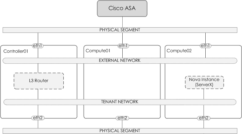
Components
Before we dive into the configuration steps, lets quickly look at each of the components that we will use to build our topology,
- External network – The external network allows for ‘external’ connectivity to the neutron (i.e L3) router. In turn allowing (via floating IPs) access into the instance.
- Tenant network – The network that your virtual instances will reside on.
- L3 Router – An L3 router, much like a physical router provides connectivity between networks and is also able to perform network address translation (NAT).
- Floating IPs – Floating IPs are synonymous to Static NAT i.e they provide a 1-to-1 mapping. This provides the ability for inbound connectivity from the external network into the instance.
Physical Gateway
Before we start with configuring Neutron, the physical gateway (in our case a Cisco ASA5505) is configured to provide remote connectivity. Within our configuration we simply configure a trunk and the corresponding VLAN (i.e the provider segment aka VLAN 50).
interface Ethernet0/4
  description ## OPENSTACK TRUNK ##
  switchport trunk allowed vlan 50
  switchport trunk native vlan 1
  switchport mode trunk
  speed 100
  duplex full
!
interface Vlan50
  nameif OPENSTACK-EXTERNAL-NET
  security-level 100
  ip address 172.29.50.1 255.255.255.0
External Network
So the first Neutron component we will configure, will be the external network. This will be a VLAN network, and will segment traffic using a VLAN tag of 50.
openstack network create --provider-network-type vlan \
                         --provider-physical-network vlan \
                         --provider-segment 50 \
                         --external \
                         --share \
                         external_network
openstack subnet create --subnet-range 172.29.50.0/24 \
                        --network external_network \
                        --no-dhcp \
                        --gateway=172.29.50.1 \
                        --allocation-pool start=172.29.50.100,end=172.29.50.110 \
                        external_subnet
NOTE I must point out the Provider Physical Network option.
Many of you may be asking, What do I add for ‘–provider-physical-network’ when configuring the network? This is defined within physical_interface_mappings in linuxbridge_agent.ini or bridge_mappings within openvswitch_agent.ini.
Example below,
[linux_bridge]
physical_interface_mappings = flat:eth12,vlan:br-vlan
Tenant Network
Next we create the tenant network and tenant subnet.
openstack network create tenant_network
openstack subnet create tenant_subnet \
                        --subnet-range 10.1.1.0/24 \
                        --network tenant_network
L3 Router
Finally we create the L3 router, along with assigning the external network and tenant subnet to it.
openstack router create l3_router
openstack router set l3_router --external-gateway external_network
openstack router add subnet l3_router tenant_subnet
Next Steps
With the topology configured, you can now create an instance. Ensuring you assign it to the tenant network, and then associate a floating IP to it, in order to allow connectivity to/from your instance.

- NETCONF & YANG: Automate Network Configs via Python - April 2, 2026
- Palo Alto – How to Configure Your Next-Generation Firewall - April 2, 2026
- How to Harden Linux SSH: Keys, Fail2ban & Ciphers - March 1, 2026
Want to become an OpenStack expert ?
Here is our hand-picked selection of the best courses you can find online:
OpenStack Essentials course
Certified OpenStack Administrator course
Docker Mastery course
and our recommended certification practice exams:
Delta Practice Tests