Table of Contents
Introduction
Within this article we will walk through the various steps required in configuring MPLS.
NOTE This article does not look to explain the various terms and concepts of MPLS, for details around these please see Getting to Know MPLS.
Overview
Within our example we will have 2 customers COSTA and STARBUCKS. Each customer consisting of the endpoint addresses – 172.16.1.1 and 172.16.2.1. We will place each customer within its own VRF. Traffic will be initiated from one end of the customers site (i.e the Customer Edge). Up to the Provider Edge via the necessary VRF. From this point it will then be label switched across the MPLS core, then routed back down to the other Customer Edge. Sounds confusing? Don’t worry, we will break each part down piece by piece.
Within this tutorial our topology will be built upon on 5 key steps. They are,
- Enable MPLS.
- Configure MP-BGP.
- Configure VRFs.
- Configure CE-PE routing.
- Configure route redistribution.
Topology
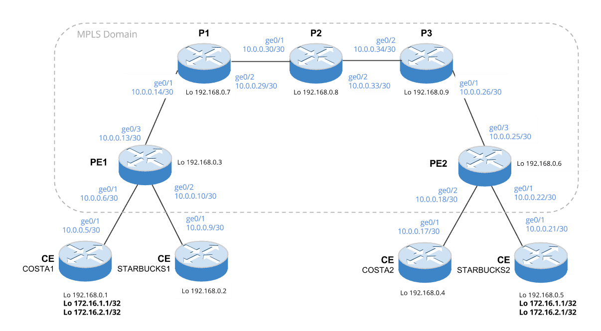
Let us look at the topology (Figure 1) we will be using within our example.
Figure 1 – Overall Topology
Additionally, Figure 2 shows how the topology will look once the VRFs and MP-BGP are configured.
Figure 2 – VRF and MP-BGP

Prerequisites
Before we start to configure MPLS there are aspects to our topology that must be configured.
- An IGP between all Provider and Provider Edge routers. In our case we use OSPF.
- Loopbacks on each router.
Enable MPLS
Ok, lets begin. First of all we will enable the Label Distribution Protocol (LDP) across our Provider and Provider-Edge routers.
This is done by enabling LDP at a global level, then enabling it on a per interface level on each interface within the MPLS domain, i.e Provider Edge to Provider and Provider to Provider. Please refer to Figure 1 for reference.
P/PE Configuration
Below shows the commands you would configure on each router within the MPLS domain.
mpls ip interface giX/X mpls ip
Verification
There are 2 commands useful for verifying your configuration.
First of all use show mpls interfaces to show which interfaces LDP is enabled on. Here is an example,
PE-1#show mpls interfaces
Interface              IP            Tunnel   BGP Static Operational
GigabitEthernet0/1     Yes (ldp)     No       No  No     Yes
GigabitEthernet0/3     Yes (ldp)     No       No  No     Yes
Then to confirm successful LDP neighbor discovery use show mpls ldp neighbor
PE-1#show mpls ldp neighbor
    Peer LDP Ident: 192.168.0.7:0; Local LDP Ident 192.168.0.3:0
        TCP connection: 192.168.0.7.34227 - 192.168.0.3.646
        State: Oper; Msgs sent/rcvd: 36/36; Downstream
        Up time: 00:14:28
        LDP discovery sources:
          GigabitEthernet0/3, Src IP addr: 10.0.0.14
        Addresses bound to peer LDP Ident:
          10.0.0.14       192.168.0.7     10.0.0.29
Configure MP-BGP
MP-BGP is used to advertise the customer routes (in our case the CE 172.16.x.x addresses) between each of the PE routers. This will ensure each PE knows the next hop (i.e the PE peers loopback address) required to get to the customers network. Traffic will then be sent over the MPLS core due to each PE having an LSP (Label Switched Path) to its peers loopback address.
Great! However, there is another point to address (excuse the pun) which is route separation. As you have seen within our topology we have 2 customers, both with the same address ranges.
In order to distinguish these routes, route distinguishers (RD) are used. This is a unique number prepended to each route within a VRF to identify it as belonging to that particular VRF or customer[1].
Why use MP-BGP and not legacy BGP?
MP-BGP supports 2 key features over legacy BGP – VPNv4 and Extended Communities.
- VPNv4 Capability – This simply means that routes containing a route distinguisher can be exchanged.
- Extended Communities – In short, these use route targets, applied to the VRF , to control the import and export of routes across the VRFs.
With all that said, lets move onto the configuration.
NOTE In the configuration below each neighbor address is the loopback of its peer.
PE-1 Configuration
router bgp 65536
 bgp log-neighbor-changes
 neighbor 192.168.0.6 remote-as 65536
 neighbor 192.168.0.6 update-source Loopback0
 !
 address-family vpnv4
  neighbor 192.168.0.6 activate
  neighbor 192.168.0.6 send-community extended
 exit-address-family
PE-2 Configuration
router bgp 65536
 bgp log-neighbor-changes
 neighbor 192.168.0.3 remote-as 65536
 neighbor 192.168.0.3 update-source Loopback0
 !
 address-family vpnv4
  neighbor 192.168.0.3 activate
  neighbor 192.168.0.3 send-community extended
 exit-address-family
Verification
To verify our configuration we will first check the adjacency via show ip bgp summary. We then confirm that MP-BGP is ready to support the additional capabilities (VPNv4) via show ip bgp neighbors | sec capabilities.
PE-1#show ip bgp summary
BGP router identifier 192.168.0.3, local AS number 65536
BGP table version is 1, main routing table version 1

Neighbor        V           AS MsgRcvd MsgSent   TblVer  InQ OutQ Up/Down  State/PfxRcd
192.168.0.6     4        65536   10029   10078        1    0    0 6d08h           0
PE-1#show ip bgp neighbors | section capabilities
  Neighbor capabilities:
    Route refresh: advertised and received(new)
    Four-octets ASN Capability: advertised and received
    Address family IPv4 Unicast: advertised and received
    Address family VPNv4 Unicast: advertised and received
    Enhanced Refresh Capability: advertised and received
    Multisession Capability:
    Stateful switchover support enabled: NO for session 1
Configure VRF’s
To separate our customers, each one will be placed into a separate VRF. Within each VRF a route distinguisher (RD), along with an import and export route target are configured.
To quickly recap,
- Route distinguishers are prepended to routes to ensure route uniqueness.
- Route targets are used by a VRF to determine which VRFs it should export or import routes to/from.
NOTE The command route-target both is used to define both the import and export route targets. These are normally defined using the route-target import and route-target export commands.
WARNING You will see in the configuration below that we readd the interface IPs. This is because the interface IP is removed at the point you apply the VRF.
PE1 Configuration
ip vrf 100:COSTA
  rd 65536:100
  route-target both 65536:100

ip vrf 200:STARBUCKS
  rd 65536:200
  route-target both 65536:200

int gi0/1
  ip vrf forwarding 100:COSTA
  ip address 10.0.0.6 255.255.255.252

int gi0/2
  ip vrf forwarding 200:STARBUCKS
  ip address 10.0.0.10 255.255.255.252
PE2 Configuration
ip vrf 100:COSTA
  rd 65536:100
  route-target both 65536:100
  exit

ip vrf 200:STARBUCKS
  rd 65536:200
  route-target both 65536:200
  exit

int gi0/1
  ip vrf forwarding 200:STARBUCKS
  ip address 10.0.0.22 255.255.255.252

int gi0/2
  ip vrf forwarding 100:COSTA
  ip address 10.0.0.18 255.255.255.252
Verification
To verify, we will simply check that the VRFs have been created, via show vrf.
PE-1#show vrf
  Name                             Default RD            Protocols   Interfaces
  100:COSTA                        65536:100             ipv4        Gi0/1
  200:STARBUCKS                    65536:200             ipv4        Gi0/2
  Mgmt-intf                        <not set>             ipv4,ipv6   Gi0/0
Configure CE-PE Routing
In order to exchange routes between the CE and PE routers, OSPF is configured.
Each CE Configuration
router ospf 1
 passive-interface Loopback0
 network 0.0.0.0 255.255.255.255 area 0
PE1 Configuration
router ospf 100 vrf 100:COSTA
  network 10.0.0.6 0.0.0.0 area 0

router ospf 200 vrf 200:STARBUCKS
  network 10.0.0.10 0.0.0.0 area 0
PE2 Configuration
router ospf 100 vrf 100:COSTA
 network 10.0.0.18 0.0.0.0 area 0

router ospf 200 vrf 200:STARBUCKS
 network 10.0.0.22 0.0.0.0 area 0
Verification
To verify that the routes are correctly being distributed we use show ip route vrf . Below we check the routes within the 200:STARBUCKS VRF.
PE-2#show ip route vrf 200:STARBUCKS

Routing Table: 200:STARBUCKS
Codes: L - local, C - connected, S - static, R - RIP, M - mobile, B - BGP
       D - EIGRP, EX - EIGRP external, O - OSPF, IA - OSPF inter area
       N1 - OSPF NSSA external type 1, N2 - OSPF NSSA external type 2
       E1 - OSPF external type 1, E2 - OSPF external type 2
       i - IS-IS, su - IS-IS summary, L1 - IS-IS level-1, L2 - IS-IS level-2
       ia - IS-IS inter area, * - candidate default, U - per-user static route
       o - ODR, P - periodic downloaded static route, H - NHRP, l - LISP
       a - application route
       + - replicated route, % - next hop override, p - overrides from PfR

Gateway of last resort is not set

      10.0.0.0/8 is variably subnetted, 2 subnets, 2 masks
C        10.0.0.20/30 is directly connected, GigabitEthernet0/1
L        10.0.0.22/32 is directly connected, GigabitEthernet0/1
      172.16.0.0/32 is subnetted, 2 subnets
O        172.16.1.1 [110/2] via 10.0.0.21, 1d02h, GigabitEthernet0/1
O        172.16.2.1 [110/2] via 10.0.0.21, 1d02h, GigabitEthernet0/1
      192.168.0.0/32 is subnetted, 1 subnets
O        192.168.0.5 [110/2] via 10.0.0.21, 1d02h, GigabitEthernet0/1
Configure Route Redistribution
It is now time for us to redistribute the routes learnt from MP-BGP back into our VRFs, along with share the VRF routes with MP-BGP.
Before we do this, lets look at the routing table for VRF 200:STARBUCKS on PE1. From the output below you can see that PE1 has no knowledge of how to get to 17.16.1.1 and 172.16.2.1.
Remember these addresses reside on CE-STARBUCKS2 connected to the PE2 router (reference Figure 1).
PE-1#show ip route vrf 200:STARBUCKS

Routing Table: 200:STARBUCKS
Codes: L - local, C - connected, S - static, R - RIP, M - mobile, B - BGP
       D - EIGRP, EX - EIGRP external, O - OSPF, IA - OSPF inter area
       N1 - OSPF NSSA external type 1, N2 - OSPF NSSA external type 2
       E1 - OSPF external type 1, E2 - OSPF external type 2
       i - IS-IS, su - IS-IS summary, L1 - IS-IS level-1, L2 - IS-IS level-2
       ia - IS-IS inter area, * - candidate default, U - per-user static route
       o - ODR, P - periodic downloaded static route, H - NHRP, l - LISP
       a - application route
       + - replicated route, % - next hop override, p - overrides from PfR

Gateway of last resort is not set

      10.0.0.0/8 is variably subnetted, 2 subnets, 2 masks
C        10.0.0.8/30 is directly connected, GigabitEthernet0/2
L        10.0.0.10/32 is directly connected, GigabitEthernet0/2
We will now configure route redistribution on PE1 and PE2.
PE1 Configuration
router bgp 65536
  address-family ipv4 vrf 100:COSTA
    redistribute ospf 100 vrf 100:COSTA

router ospf 100 vrf 100:COSTA
  redistribute bgp 65536 subnets

router bgp 65536
  address-family ipv4 vrf 200:STARBUCKS
    redistribute ospf 200 vrf 200:STARBUCKS

router ospf 200 vrf 200:STARBUCKS
  redistribute bgp 65536 subnets
PE2 Configuration
router bgp 65536
  address-family ipv4 vrf 100:COSTA
    redistribute ospf 100 vrf 100:COSTA

router ospf 100 vrf 100:COSTA
  redistribute bgp 65536 subnets

router bgp 65536
  address-family ipv4 vrf 200:STARBUCKS
    redistribute ospf 200 vrf 200:STARBUCKS

router ospf 200 vrf 200:STARBUCKS
  redistribute bgp 65536 subnets
Verification
If we now check our VRF routing table, you will see that the 172.16.1.1 and 172.16.2.1 addresses have been learnt via MP-BGP.
PE-1#show ip route vrf 200:STARBUCKS | inc 172.16.[1-2]
B        172.16.1.1 [200/2] via 192.168.0.6, 00:04:24
B        172.16.2.1 [200/2] via 192.168.0.6, 00:04:24
But wait, what is the next hop? Thats right, it is the other PE routers loopback. And how do we get there? BINGO, via the MPLS core.
We can further confirm this by checking the MPLS forwarding table and/or CEF. Like so,
PE-1#show mpls forwarding-table 192.168.0.6
Local      Outgoing   Prefix           Bytes Label   Outgoing   Next Hop
Label      Label      or Tunnel Id     Switched      interface
20         19         192.168.0.6/32   0             Gi0/3      10.0.0.14
PE-1#show ip cef vrf 200:STARBUCKS  172.16.1.1 detail
172.16.1.1/32, epoch 0, flags [rib defined all labels]
  recursive via 192.168.0.6 label 26
    nexthop 10.0.0.14 GigabitEthernet0/3 label 19
Final Validation
As a final validation, to confirm connectivity from CE to CE and to also show the path of the traffic is going via the MPLS core we will perform a ping and traceroute.
COSTA2#ping 172.16.1.1
Type escape sequence to abort.
Sending 5, 100-byte ICMP Echos to 172.16.1.1, timeout is 2 seconds:
!!!!!
Success rate is 100 percent (5/5), round-trip min/avg/max = 8/10/13 ms

COSTA2#traceroute 172.16.1.1
Type escape sequence to abort.
Tracing the route to 172.16.1.1
VRF info: (vrf in name/id, vrf out name/id)
  1 10.0.0.18 3 msec 4 msec 5 msec
  2 10.0.0.26 [MPLS: Labels 20/24 Exp 0] 11 msec 11 msec 10 msec
  3 10.0.0.33 [MPLS: Labels 20/24 Exp 0] 10 msec 9 msec 9 msec
  4 10.0.0.29 [MPLS: Labels 16/24 Exp 0] 9 msec 11 msec 12 msec
  5 10.0.0.6 [MPLS: Label 24 Exp 0] 7 msec 9 msec 8 msec
  6 10.0.0.5 9 msec *  10 msec
STARBUCKS1#ping 172.16.1.1
Type escape sequence to abort.
Sending 5, 100-byte ICMP Echos to 172.16.1.1, timeout is 2 seconds:
!!!!!
Success rate is 100 percent (5/5), round-trip min/avg/max = 8/9/12 ms

STARBUCKS1#traceroute 172.16.1.1
Type escape sequence to abort.
Tracing the route to 172.16.1.1
VRF info: (vrf in name/id, vrf out name/id)
  1 10.0.0.10 4 msec 4 msec 3 msec
  2 10.0.0.14 [MPLS: Labels 19/26 Exp 0] 11 msec 13 msec 11 msec
  3 10.0.0.30 [MPLS: Labels 17/26 Exp 0] 8 msec 11 msec 7 msec
  4 10.0.0.34 [MPLS: Labels 17/26 Exp 0] 11 msec 9 msec 8 msec
  5 10.0.0.22 [MPLS: Label 26 Exp 0] 10 msec 11 msec 9 msec
  6 10.0.0.21 8 msec *  11 msec
Sources
[1] http://packetlife.net/blog/2013/jun/10/route-distinguishers-and-route-targets/

- NETCONF & YANG: Automate Network Configs via Python - April 2, 2026
- Palo Alto – How to Configure Your Next-Generation Firewall - April 2, 2026
- How to Harden Linux SSH: Keys, Fail2ban & Ciphers - March 1, 2026
Want to become a networking expert ?
Here is our hand-picked selection of the best courses you can find online:
Cisco CCNA Certification Gold Bootcamp
Complete Cyber Security Course – Network Security
Internet Security Deep Dive course
Python Pro Bootcamp
and our recommended certification practice exams:
Delta Practice Tests