Table of Contents
Introduction
First of all, what is a route leak?
A route leak is the propagation of routing announcement(s) beyond their intended scope – RFC7908
Within this article we will look at 2 methods of route leaking within an MPLS environment – static routes and route maps. To demonstrate both methods we will look at 2 different scenarios.
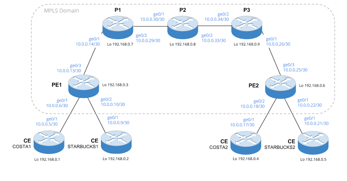
NOTE Our scenarios will be based upon Figure 1. Also please be aware that within Figure 1 OSPF has been configured as the IGP across the entire topology.
Figure 1 – Example Topology.
Static Routes
The first method that we will look at are static routes. Static routes are created and then redistributed into the necessary IGP instance(s), in our case OSPF.
Example
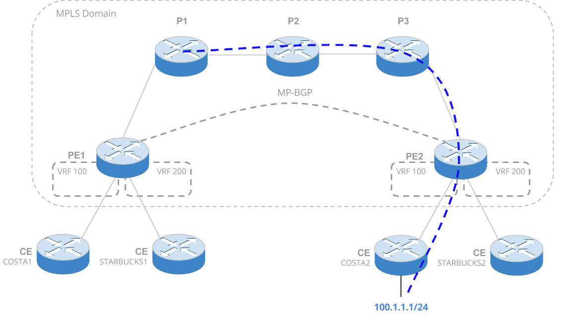
Within our example we will configure route leaking in order for our Provider 1 router to access a resource from within our customer site – CE COSTA1.
Figure 2. CE from Provider router.
Configuration
PE2 – Redistribute Route to CE
The first part of the configuration that isrequired, will be to create a static route on the PE2 router. We then redistribute the route into OSPF so that P1 is aware.
ip route 100.1.1.0 255.255.255.0 GigabitEthernet0/2 10.0.0.17 router ospf 1 redistribute static subnets
PE2 – Redistribute Route Back to Provider
Next we create a route to point back to P1. We then redistribute this route into the OSPF VRF instance, to ensure the route is propagated back to our CE.
ip route vrf 100:COSTA 10.0.0.28 255.255.255.252 GigabitEthernet0/3 10.0.0.26

router ospf 100 vrf 100:COSTA
 redistribute static subnets
Route Maps
Next let us look at route maps.
A route map defines which of the routes from the specified routing protocol are allowed to be redistributed into the target routing process.
Now, to demonstrate route maps lets look at an example.
Example
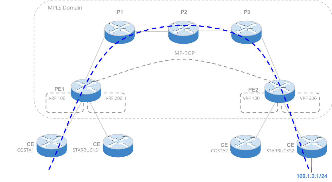
Within this example a customer will create a new network. This network will be leaked to another customer. The interesting part to this is as both customers reside within separate VRFs on the Provider Edge routers we will need to route leak between VRFs.
Figure 3. CE to CE between customer VRFs.
Before we look at the configuration. Lets break it down.
- A route map is created. This defines, a) a prefix list that defines the route set for redistribution b) a route target.
- We then assign the export map to our VRF.
- This configuration now reads – if the prefix-list matches a route within the routing table for the given VRF, then redistribute the route into BGP, affixing the route target to the route.
- We then configure the other VRF (on PE1) to import routes that contain the route target.
Configuration
PE2 – Export
ip prefix-list EXPORT_LIST_VRF200 seq 5 permit 100.1.1.0/24

route-map EXPORT_MAP_VRF200_TO_BGP permit 10
 match ip address prefix-list EXPORT_LIST_VRF200
 set extcommunity rt 3:3 additive

ip vrf 200:STARBUCKS
  export map EXPORT_MAP_VRF200_TO_BGP
PE1 – Import
ip vrf 100:COSTA
 route-target import 3:3

- NETCONF & YANG: Automate Network Configs via Python - April 2, 2026
- Palo Alto – How to Configure Your Next-Generation Firewall - April 2, 2026
- How to Harden Linux SSH: Keys, Fail2ban & Ciphers - March 1, 2026
Want to become a networking expert ?
Here is our hand-picked selection of the best courses you can find online:
Cisco CCNA Certification Gold Bootcamp
Complete Cyber Security Course – Network Security
Internet Security Deep Dive course
Python Pro Bootcamp
and our recommended certification practice exams:
Delta Practice Tests