One of the new features, within v11.x of the Traffic Management Operating System (TMOS) is Device Service Clustering (DSC). Over the previous HA (High Availability) features within v10.x, i.e active-standby, connection mirroring etc., DSC also provides the ability to perform,
- multi-node clustering,
- Active-Active (and Active-Standby) setup,
- greater granularity over which data is synchronized
Table of Contents
Scope
Within this article we will explain the key components to DSC, the configuration steps and also the main commands used to troubleshoot problems.
Components
DSC is built upon 5 main components. They are,
- Devices – Represents either a physical or virtual instance of a BigIP system.
- Device Groups – A group of devices that synchronize and (based on the device group type) also failover their configuration. There are 2 types of device groups,
- Sync-Failover – Both the configuration data and the failover objects are synchronized ; Utilizes traffic groups (i.e failover objects).
- Sync-Only – Only the configuration data is synchronised.
- Traffic Groups – A collection of failover objects (i.e virtual server, self IP) that runs on one of the devices within the (Sync-Failover) Device Group. Should the device become unavailable the failover object is the served by the other device within the Device Group.
- Device Trust – Represents a trust relationship between devices also known as a trust domain. This is achieved via certificate based authentication. Device Trust is a prerequisite for both device groups and traffic groups.
Note : The initial trust of each device is performed over the management interface.
- Folders – Folders contain configuration objects for the necessary partition in which they reside. This provides greater granularity over what configuration that you decide to synchronize between devices. Both the default and the top level folder is root.
Note : Each of these items can be located via the GUI under ‘Device Management’.
Synchronization
Unlike v10.x and below, TMOS v11 now uses rsync internally to perform synchronization between devices. Also unlike v10 which used tcp/443 for synchronizing data, v11 uses tcp/4353.
The available options and also the ways in which you can issue a synchronization.
Options
The various options for synchronization can be found under ‘Device Groups’ and ‘Devices’.
Device Groups
- Automatic Sync (via Properties Panel) – Automatically synchronize objects between devices based on the modified time. The most recently modified object is synchronized to the other device. Because the modified time is used as the trigger NTP (i.e time synchronization) must be configured.
- Full Sync (via Properties Panel) – Rather then only synchronizing the configuration objects that have been modified, the whole configuration is synchronized.
- Network Failover (via Failover Panel) – Determines whether a network probe is sent between the devices to ensure neighbor status. This is instead of uses cable based failover*.
* As cable based failover mandates only 1 device can ever be active cable based failover doesn’t support an Active-Active based setup (i.e more then 2 traffic groups).
Devices
- Config Sync (via Device Connectivity) – Defines which interface is used for synchronization. Its recommended by F5 that this is a dedicated link.
- Failover (via Device Connectivity) – Defines which port is used for the network failover probes.
- Mirroring (via Device Connectivity) – Defines which interfaces are used for mirroring. It is recommended that a secondary address is also configured to provide redundancy should the primary fail.
Issuing a Sync
Manual DSC synchronization can be performed via either the command line or the WebUI. To perform a manual synchronization within the WebUI go to ‘Device Management / Overview’. From this screen you will be presented with an overview of the synchronization state across your devices and device groups.
The will also see the following options,
- Sync Device to Group – Synchronizes any objects that have been recently modified to the other devices within the device group.
- Sync Group to Device – Synchronizes any objects that have been recently modified from the devices within the group.
- Overwrite Configuration – When performing the above action(s) synchronize the configuration regardless of when it has been modified.
Deployment Modes
There are 2 main types of deployment modes with DSC, Active-Standby and Active-Active.
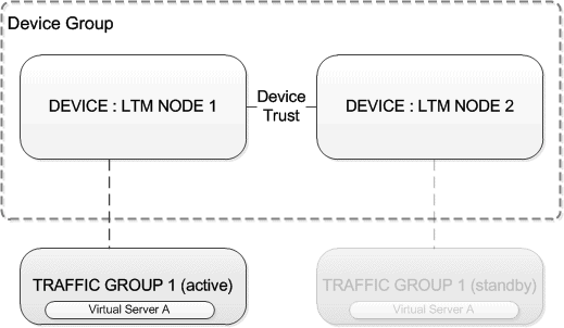
Active-Standby
With an Active-Standby based deployment traffic is only processed by a single device. This is achieved via single traffic group, which all failover objects (virtual servers, self-ips etc) reside within. This traffic group is then active on one of the nodes. Should this node fail its HA checks the traffic group will be marked as standby and the traffic group on the other node promoted to active.
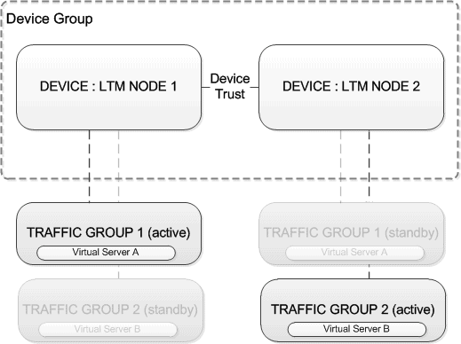
Active-Active
With an Active-Active based deployment traffic is processed by both devices. This is achieved via 2 Traffic Groups, (based on the example below) one Traffic Group is placed as active on Node 1 and the other as active on Node 2. Your failover objects are then assigned to either of the traffic groups, i.e Virtual Server A in traffic group 1 and then Virtual Server B in Traffic Group 2.
This results in Node 1 processing traffic for Virtual Server A, and Node 2 processing traffic for Virtual Server B.
Note : It is important to ensure that both nodes are running under 50% capacity. This ensures if either of the devices fail then at the point all traffic is processed by the single node that the devices capacity is not reached.
Configuration
Device Trust
- Goto ‘Device Management’ / ‘Device Trust’ / ‘Peer List’.
- Click ‘Add’.
- Enter the IP and credentials of the peer device.
- Click ‘Retrieve Device Information’
Device Group
- Goto ‘Device Management’ / ‘Device Groups’.
- Click ‘Create’.
- Enter name, select ‘Sync-Failover’ as the ‘Group Type’, and then add all devices to the ‘Included’ members list.
- Enable ‘Network Failover’.
Synchronize
- Goto ‘Device Management’ / ‘Overview’.
- Click ‘Sync Device to Group’.
- Click ‘Sync’.
- Wait for the Sync Status of both devices to turn green.
Active-Standby
Once the trust domain is configured the floating IP for each VLAN needs to be configured.
Assign Traffic Group 1
- Goto ‘Network’ / ‘Self IPs’.
- Create a floating Self IP for each VLAN (i.e Internal and External).
- For each self IP created configure the ‘Traffic Group’ as ‘traffic-group1-floating’.
In this example we will only be using a single Traffic Group, because of this any virtual servers that are created will be placed into the default (single traffic group).
Note : Should you require MAC Masquerading, a single traffic group can still be used. However this will result in the same MAC address being advertised for all Self-IPs within the traffic group which may complicate future troubleshooting.
Active-Active
Once the trust domain is configured the floating IP for each VLAN needs to be configured. Once done an additional traffic group is also created.
Assign Traffic Group 1
- Goto ‘Network’ / ‘Self IPs’.
- Create a floating Self IP for each VLAN (i.e Internal and External).
- For each self IP created configure the ‘Traffic Group’ as ‘traffic-group1-floating’.
Create Traffic Group 2
- Goto ‘Device Management’ / ‘Traffic Groups’.
- Create a new Traffic Group called ‘traffic-group-2’ using all the default settings.
Demote Traffic Group 2
- Select ‘traffic-group-2’ from the list and select ‘Force to Standby’.
The traffic group list will now show your current device running 1 traffic group as active and 1 traffic group as standby.
Assign Traffic Group 2
- Via ‘Local Traffic / Virtual Servers / Virtual Address List’ select the Virtual Server that you want to assign to ‘traffic-group-2’.
- Via ‘Local Traffic / Virtual Servers / Virtual Server List’ select your Virtual Server. Within the traffic group section select ‘traffic-group-2’.
Enable SNAT
- Under ‘Source Address Translation’ select Automap*.
Once complete the default traffic-group will be active on one node and traffic-group-2 will be active on the node.
*As the SelfIP is assigned to traffic-group-1 without Automap the traffic would be sent through the wrong device.
VE Issues
When configuring DSC on Virtual LTMs (when using the steps above) you may find that both sides show as disconnected. I have only found this in the lab for VE devices on both v11.4 and v11.5.
To resolve this you will need to change each of the devices certificates to a self-signed certificate and also perform the steps in a slighty different order.
Steps
Below provides a summary of the required steps.
- Generate new self signed cert for each device – Goto Device Management / Device Trust / Local Domain. Select “Generate New Self-Sign Authority”.
- Create Sync Interface – Create a new VLAN that will be used for synchronization, mirroring, and network failover on both devices.
- Configure ConfigSync/Mirroring – Configure the interfaces that will be used for mirroring, config sync and network failover on both devices.
- Configure Device Group – Create a Sync-Failover device group on Node 1 and only add local device. Enable Network Failover.
- Configure Trust – On Node 1 configure the Trust Domain.
- Update Device Group – On Node 1 add the remote peer to the device group.
- Traffic Group Assignment – Assign the traffic groups accordingly.
- Synchronize – One Node 1 perform an initial synchronization via Sync Device to Group in “Device Management’ / ‘Overview”.
Troubleshooting
Checks
If your are facing issues with your HA setup, the following should be checked,
- Verify NTP is working correctly.
- Check connectivity between peer addresses.
- Check Self IPs used as peer addresses reside in route domain 0.
- Ensure the following protocols/ports are permitted between nodes. Note : No matter which Port lockdown setting used these ports are permitted.
- UDP/1026 (network failover)
- TCP/1028 (connection & persistence mirroring)
- TCP/4353 (CMI – peer communication)
- Reset and Rebuild your Trust Domain.
Commands
tmsh run /cm sniff-updates
tmsh run /cm config-sync
tmsh run /cm watch-devicegroup-device
tmsh run /cm watch-sys-device
tmsh run /cm watch-trafficgroup-device

tmsh show /cm traffic-group
tmsh show /cm sync-status
References
http://support.f5.com/kb/en-us/solutions/public/13000/900/sol13946.html

- NETCONF & YANG: Automate Network Configs via Python - April 2, 2026
- Palo Alto – How to Configure Your Next-Generation Firewall - April 2, 2026
- How to Harden Linux SSH: Keys, Fail2ban & Ciphers - March 1, 2026
Want to become a Loadbalancers expert ?
Here is our hand-picked selection of the best courses you can find online:
F5 BIG-IP 101 Certification Exam – Complete Course
F5 BIG-IP 201 Certification Exam – Complete Course
and our recommended certification practice exams:
Delta Practice Tests