Table of Contents
Introduction
Within this article we will take an in-depth look into the architecture of the Cisco ASA 5585X.
CHASSIS
The Cisco ASA 558X is a chassis based firewall. The chassis consists of 2 slots, each slot can be populated with either an SSP (Security Services Processor) or Interface Module (ASA5585-NM-XX).
The SSPs come in various models – SSP10, SSP20, SSP40 and SSP60. With each SSP ranging in varying specification depending on the amount of traffic that you need to process.
There are 4 types of SSP. They are,
- SSP-XX FW/VPN
- SSP-XX IPS
- SSP-XX CX
- SSP-XX FIREpower (will replace IPS/CX which are going EOL)
Based on their being 2 slots and various SSP types this can raise some questions. Below looks to answer some of the commonly asked questions around the 5585X chassis and SSP’s.
- The SSP-XX FW/VPN must always be present in slot0.
- A maximum of 2 interface modules can be installed into slot1.
- If only one 1 interface module is installed a slot divider is required. This is needed for air flow.
- The Security Plus license is required for the SSP10 and SSP20 in order to enable the 10Gb ports, This includes the integrated ports.
- 2 x FW/VPN SSPs can be installed within a single chassis, however each SSP will be seen as an individual firewall. This, in turn allows you to cluster the 2.
Architecture
The ASA5585X architecture is very different to that of the ASA5500X family. How, you may ask ? Let me explain.
DATA_PATH
Before we begin we should really take a moment to mention the DATA_PATH thread. These threads are spawned from the Dispatch_Unit process with each core running a DATA_PATH thread. Each core/DATA_PATH thread walks the rings looking for packets. The core locks to the ring, until it has pulled all of the packets into software for further processing.
ASA5500-X
First of all lets look at the architecture of an ASA5500-X. Each external port is attached to the NIC. With each NIC containing a single RX/TX ring.
Based on the diagram below lets look at the path of an ingress packet,
- The packet enters one of the onboard 1Gb ports.
- The packet is sent to the RX ring.
- A CPU core (DATA_PATH thread) then pulls the packet from the ring and passed it into software for processing.
NOTE For simplicity only the RX rings are shown in the diagrams. In reality there are the same amount of TX rings as there are RX rings present.
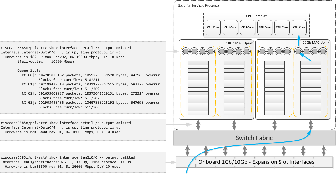
5585X
The 5585X is built around a distributed architecture model. There are 4 main components,
- External Ports – The physical port that receives the frame.
- Switch Fabric – Linked to the external ports. The switch fabric also has multiple uplinks to the MAC uplinks.
- 10Gb MAC Uplinks – Each MAC uplink contains multiple TX/RX rings and FIFO queues. These are grouped, i.e a set of TX/RX rings are grouped to a single FIFO queue. The total number of MAC Uplinks and TX/RX rings is dependent on the SSP model.
- CPU Complex – Contains the CPU cores. The total number of cores is dependent on the SSP model.
NOTE Both the MAC Uplinks and the CPU complex are physically located on the SSP.
Now that you we have covered the main components. To full understand how they inter-operate lets looks at how an ingress packet is processed.
- The packet enters one of the external ports and is passed to the switch fabric.
- A hash is created based on the source/destination IP and also the source/destination port of the packet.
- Next an uplink and RX ring is selected. The packet is then sent from the switch fabric to the selected uplink.
- The packet processed through upto the selected RX ring.
- The packet is then pulled from the RX ring by the CPU (DATA_PATH thread) into software for processing.
- Further packets are persisted to the same uplink/ring based on the previously created hash.
Caveats
Though the architecture has been designed for performance, the following caveats should be noted,
- A single flow can end up on a single core. This isn’t ideal when is comes to super flows (i.e traffic streams that microburst). This can lead to overruns on the RX rings as the CPU core is unable keep up with the packet rate.
- Because the ring buffers do not reside on the external facing interfaces (i.e show interface te0/6). Interface errors are viewed from within the MAC Uplink (i.e show interface internal-data0/0 etc).
- Flow Control is supported, but due to the distributed architect model the implementation of this feature is slightly different. Flow control is still configured on the external facing interface however as the interfaces do not have the ring buffers attached the configurable watermark options are not available. It is also worth noting though the defaults are 64KB low, 128KB high, 26624 time units, these defaults are the same as the 5580.
Buffer Blocks
One quick point around buffer blocks. The flows previously mentioned reference the packets being pulled from the rings via the cores. Though ,in essence true this process has been simplified for ease of explanation throughout this article.
From RX ring to CPU complex here is a full breakdown,
- The CPU complex instructs the RX ring with the memory locations where the ingress packet should be stored.
- The RX ring populates these memory locations (blocks) with the ingress packets.
- These packets are then pulled from the memory blocks by the CPU complex for processing.
- The memory blocks are then refilled by the RX ring with new ingress packets.
ASP Loadbalacing
As previously mentioned the cores lock to a ring until the ring is empty. To change this behavior the command asp load-balanceis used.
It is recommended to change the default ASP Loadbalancing behavior when any of the following is observed,
- uneven usage across the cores
- overruns seen on the RX rings even though the CPU usage appears low. Typically seen with traffic microbursts
There are 2 options when configuring ASP loadbalancing. They are,
Per-Packet – Each core i.e DATA_PATH thread locks to the ring on a per packet basis.
ciscoasa5585x/pri/act(config)# asp load-balance per-packet
Per-Packet-Auto – Introduced within 9.3(1) allows the ASA to adaptively switch asp loadbalance per packet on and off. Further details around this command can be found here.
ciscoasa5585x/pri/act(config)# asp load-balance per-packet-auto
References

- NETCONF & YANG: Automate Network Configs via Python - April 2, 2026
- Palo Alto – How to Configure Your Next-Generation Firewall - April 2, 2026
- How to Harden Linux SSH: Keys, Fail2ban & Ciphers - March 1, 2026
Want to become an IT Security expert ?
Here is our hand-picked selection of the best courses you can find online:
Internet Security Deep Dive course
Complete Cyber Security Course – Hackers Exposed
CompTIA Security+ (SY0-601) Certification Complete course
and our recommended certification practice exams:
Delta Practice Tests